
Medical Technology: Stainless Steel Sheet Metal Parts – Precisely Manufactured, Hygienic, and Documented
BVS Blechtechnik specializes in the manufacture of medical-grade stainless steel sheet metal parts. The company focuses on precise edge finishing, controlled welding processes, hygienic surfaces, and fully documented manufacturing steps.
A sheet metal part used in a medical device will eventually come into direct contact with a patient. This fact changes the perspective on manufacturing. A sharp edge, an overlooked discoloration after welding, or microscopic roughness are quality defects in many industries that affect the next step in the process. In the case of medical technology sheet metal parts, however, precisely such areas can become sites where bacteria colonize and cannot be completely removed by cleaning alone.
This changes the requirements for established manufacturing processes. Laser cutting, bending, welding, deburring, and surface treatment are essentially the same processes as in other industrial sectors. However, the significantly higher requirements for precision, reproducibility, and surface quality—as well as the consistent documentation of every single manufacturing step—are crucial.
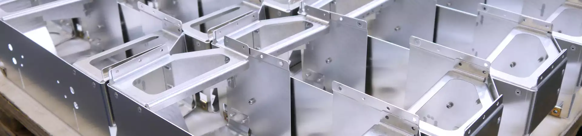
BVS Blechtechnik manufactures medical-grade sheet metal parts with the highest precision.
Surface Quality and Edge Finishing for Medical Technology Sheet Metal Parts
Thanks to its chromium oxide passive layer, stainless steel is naturally corrosion-resistant, and its smooth surface provides little opportunity for bacteria to adhere. For this reason, the material is particularly well-suited for medical technology. However, both of these properties can be lost due to improper machining.
Sharp edges, micro-gaps, and rough surfaces make it difficult to clean medical technology sheet metal parts hygienically. Bacteria can accumulate in these areas, where cleaning and disinfecting agents have limited access. For this reason, all cut edges, bent edges, and joints are systematically deburred and rounded off after machining. This step is an integral part of the manufacturing process and is not an optional post-processing step. At BVS Blechtechnik, edge finishing is defined as a fixed, documented process step and is reproducible regardless of the operator.
The choice of cutting gas in laser cutting also affects surface quality. Using nitrogen as an inert gas prevents oxidation of the cut edge. The edge remains free of oxide layers, which is important for subsequent surface treatments and for ease of cleaning during operation.
Corrosion Protection for Welded and Cut Edges
Under normal conditions, the passive layer of stainless steel regenerates on its own. However, the heat generated during welding causes localized changes to it. This is in addition to oxidation at the weld seam and on the adjacent surface. In both cases, a so-called “temper color” develops—a discoloration ranging from straw yellow to bluish-violet—which indicates that the material in this area is depleted of chromium and that corrosion protection has been weakened.
What appears to be merely discoloration is, in fact, a functional problem. In medical technology, temper marks that are not removed can lead to corrosion, particle formation, and cleaning problems over the long term. For medical device sheet metal parts that regularly come into contact with aggressive disinfectants and cleaning agents, this weakened area is unacceptable, which is why the temper color must be removed through pickling or blasting.
- Pickling chemically removes the tempered color and allows the passive layer to reform.
- The blasting removes them mechanically, and the passive layer then reforms as well.
Both methods restore the corrosion resistance that medical technology applications depend on. At BVS Blechtechnik, edge finishing is defined as a fixed, documented process step and is reproducible regardless of the operator.
Laser Welding as the Standard
Welding stainless steel parts using conventional methods such as MIG/MAG introduces a significant amount of heat into the component. In the case of thin-walled parts, this leads to warping, which is virtually impossible to correct in precision components without compromising quality. For medical technology sheet metal parts that must meet tight dimensional tolerances and be installed in compact devices, this is a fundamental problem.
Laser welding achieves this through precisely applied, minimal heat input. The heat-affected zone remains narrow, the weld seam is tight and clean, and distortion is minimal. BVS Blechtechnik relies on laser welding as standard for welding medical technology sheet metal parts in order to minimize distortion and ensure reproducible welds for quality documentation. Robot-controlled laser systems operate with identical parameters and produce every weld under the same conditions for production runs. This is an essential prerequisite for the comprehensive quality documentation required in the medical technology industry.
Electropolishing for Smooth and Durable Stainless Steel Surfaces
Not every surface that looks good actually is. Especially for components subjected to repeated cleaning and sterilization cycles, electropolishing is crucial for long-term stability and hygiene. Stainless steel that has been deburred, cut, and welded may appear flawless macroscopically but may exhibit microscopic roughness that is insufficient for hygienically critical applications. This is exactly where electropolishing comes into play.
The electrochemical process smooths stainless steel surfaces at the microscopic level. Roughness peaks are removed, the Ra value decreases, and the surface becomes more uniform. Micro-indentations where bacteria and germs could accumulate are eliminated. Foreign particles and localized weak spots in the surface are removed, resulting in a more homogeneous passive layer and increased resistance to aggressive cleaners and disinfectants.
Whether electropolishing is necessary for a specific component depends on the application and the customer’s requirements. The decisive factors are the hygiene requirements of the end product, the sterilization methods used, and the required level of cleanability.
Design Challenges in Compact Devices
Medical devices are getting smaller. At the same time, the demands on dimensional accuracy and ease of assembly are increasing. Anyone who designs medical technology sheet metal parts for tight installation spaces quickly realizes that it’s not enough to simply manufacture individual parts to exact dimensions. That’s why we support our customers as early as the design phase with feedback based on real-world manufacturing conditions.
Tolerances must be selected so that all parts can be assembled with a precise fit, even if dimensional deviations accumulate across multiple components. Questions regarding accessibility for cleaning and maintenance must be answered before the drawing is approved. If these questions are not addressed until assembly, resolving them will require significantly more effort and rework.
Quality assurance throughout the entire manufacturing process
In medical technology, quality cannot simply be taken for granted. It must be clearly demonstrated through measurement, documentation, and reproducible processes.
That is why quality assurance for medical technology sheet metal parts does not begin at the end of production, but rather before the start of series production. First, the component is produced as a prototype and fully measured. All relevant dimensions are documented in an initial prototype inspection report. Deviations are recorded and corrected as needed before series production is approved. BVS Blechtechnik documents all quality-relevant manufacturing steps in a transparent and traceable manner—from the initial prototype to series production.
Quality assurance remains a continuous process even during ongoing production. Full measurements conducted throughout series production comprehensively record all relevant dimensions on defined test parts, rather than just sampling individual features. The measurement results are documented in a traceable manner and can be retrieved at any time. This level of effort is unusual in standard manufacturing but is necessary in medical technology because defective parts in medical devices can have immediate consequences.
Precision and cleanability as a common requirement
A medical technology sheet metal part is not a finished product. It becomes part of something that supports people during critical moments in their lives. This isn’t just rhetoric; it’s the reason why every edge is deburred, every annealing mark is removed, and every weld is documented.
These requirements cannot be added later. They must be incorporated from the very beginning into the design, material selection, and production planning. BVS Blechtechnik is a manufacturing partner for medical technology sheet metal parts made of stainless steel—from design evaluation and prototyping to documented series production.
FAQ
Why do the edges of medical technology sheet metal parts require special processing?
Sharp edges and micro-gaps provide hiding places for bacteria that cannot be fully reached through cleaning and disinfection. Consistent deburring eliminates sharp transitions. This meets hygiene requirements and, at the same time, facilitates cleaning during operation.
Why is laser welding the preferred method for manufacturing medical technology sheet metal parts made of stainless steel?
Traditional welding processes introduce a significant amount of heat into the component, which causes warping in thin-walled stainless steel parts. Laser welding involves minimal heat input, produces tight, clean welds, and delivers reproducible results in automated systems. Both are essential in medical technology: dimensionally accurate parts and comprehensive quality documentation.
What is the cause of the discoloration, and why does it need to be removed?
After welding or laser cutting stainless steel, a color known as “temper color” appears, ranging from straw yellow to bluish-violet. This indicates that the protective chromium oxide passive layer has been weakened by localized heat or oxidation. Corrosion sets in earlier at these spots. For medical technology sheet metal parts that are exposed to aggressive cleaning agents, the temper color must be removed by pickling or blasting.
When is electropolishing appropriate for sheet metal parts used in medical technology?
That depends on the application and the hygiene requirements of the end product. Electropolishing smooths the stainless steel surface at the microscopic level, reduces areas where germs can adhere, and improves the uniformity of the passive layer. Whether it is necessary depends on the sterilization procedures and cleaning requirements that apply to the specific device. The decision is made jointly with the customer during the consultation phase.
How does quality assurance for medical technology sheet metal parts differ from that of standard manufacturing?
In medical technology, quality assurance begins with prototype production and a comprehensive initial prototype inspection report. During ongoing series production, full dimensional inspections are conducted throughout the production run, during which all relevant dimensions on defined test parts are fully recorded. This level of effort is not common in standard manufacturing, but it is necessary in medical technology because defective parts in medical devices can have immediate consequences.
What standards and documentation does BVS Blechtechnik support?
BVS Blechtechnik is certified to ISO 9001:2015. In addition, the company takes individual manufacturer and customer standards into account, for example when dealing with defect patterns, complaints, and the handling of defective parts. Project-specific, customized quality agreements are coordinated directly with the customer upon request.
Why are industry knowledge and experience in medical technology particularly in demand?
This highly complex industry is subject to numerous regulatory, technical, and documentation requirements. In-depth industry knowledge facilitates their reliable implementation. BVS Blechtechnik brings to the table many years of manufacturing experience and a well-established network of specialized partners.
About us
RECHTLICHES
News


Contact